Building Levels, Part 3
Rendering
Lots of progress lately actually, most of it pertaining to levels and the rendering thereof. The way I have it set up right now, is I have an object called stage (representing the viewport, or the visible contents of the level) which holds arrays with all the objects that are going to be rendered. It also holds values for the size of the viewport and the scroll position of the stage, relative to the size of the entire level. Every frame, the objects inside the arrays are drawn.
When the level is loaded, I check the starting position of the player avatar, calculate which parts of the level - which chunks - are supposed to be visible, generate those, and add them to the stage.
Every chunk is just a randomly determined color at this point. Just making sure my basic idea worked.
Every frame update, I check the current scroll position of the stage, and make the calculation again. If there are new chunks that should be visible, those are added to the stage. If there are others that are no longer visible, those are removed.
I don’t know if there are any tangible performance benefits to doing it this way, but it does add an extra layer of randomness to the levels, with the terrain changing slightly but not dramatically whenever you leave and come back, which was something I wanted to add in.
The Real Line
I’ve also made some progress with the actual rendering of the level chunks. When a chunk is generated, it is fed a descriptor and x, y coordinates. The descriptor is something like _4 or -36 or |46, and the x, y coordinates are simply the chunk position in the level matrix. The coordinates are used with the stage scroll position to determine where on the screen to draw the chunk, and the descriptor is used to generate what I’ve been calling the real line of the chunk.
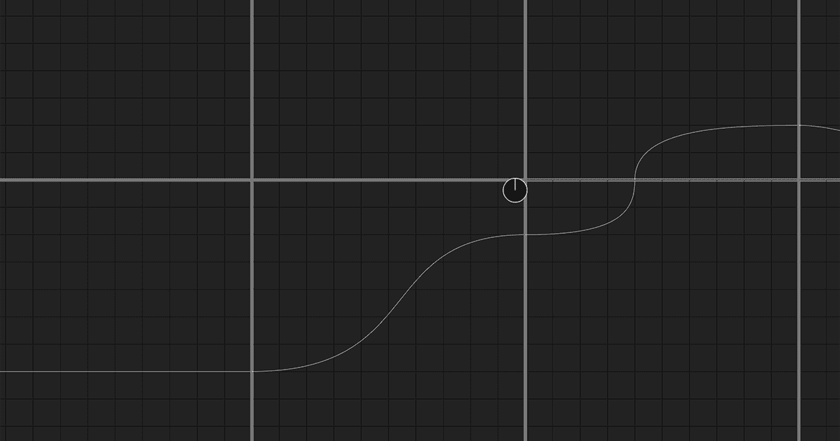
The real line represents the general contour of the ground in the chunk, and I hope I will eventually be able to use it for collision detection. Getting into specifics, the line is a Bézier curve that is based on the values received in the chunk descriptor, with a bit of randomness added in (determined at the point the chunk is generated—so as not to cause the terrain to change shape every frame). For the ones I’ve built so far (at the time of this writing), it’s been easy to define a line with just a start point, an end point and two control points.

Here’s what a level with just the real line looks like in the game as of the latest version:
A Case Study: )XY
Here are the details on the )XY terrain type. This represents a slope coming from the chunk above the current chunk, leading to the chunk to the right of the current chunk. The first digit represents where on the x-axis the slope should begin. The second, where on the y-axis the slope should end. I only need one coordinate per point, because the start point is always going to be on the top edge, and the end point always on the right. The control points are determined with a bit of randomness, but I still want some bounds on that randomness. In this case, I want to prevent the control points from ever causing the line to go outside of the chunk.
For the first control point, I take the x-coordinate from the curve start point, and the y-coordinate is determined by first setting a minimum value of 1/3 of the end point’s y-coordinate, and adding to it a random number between 0 and 2/3 of the end point’s y-coordinate.
This means there will always be some slight distance between the start point and the first control point to ensure a smooth transition from the previous chunk, but that there will never be a line that curves past the end point’s y-coordinate.
XY` calculation")
For the second control point, I set a lower bound of the x-coordinate from the start point, and add to that a random value between 0 and 2/3 of the difference of 10 and the start points x-coordinate.
XY` with randomly determined start and end points")
Looking forward
At the moment I have two terrain types planned, ^ (hill) and v (pit), that require more points than those four. To render these the way I want them, I would need a total of 7 points, and 2 Bézier curves, like so:

I’m sure there will be more terrain types later on that require this kind of curve, or even ones with more points, especially once I start adding in underground areas. I’m still working on how I want to implement these types.
Beyond the Real Line
In the final version, I don’t think I’m going to actually render the real line. Rather I want to use it for collision detection and as a guide for drawing out the visible parts of the terrain. My current thinking is that I’ll have both background and foreground terrain layers that are rendered behind and in front of the ship respectively. These will have some bumps and irregularities to make it a bit more visually interesting and will also have trees, bushes, boulders, ruins, and other stuff you might find on the ground. Probably the type of items that are rendered will be defined in the level config object. We’ll see.
All right! That’s it for now. I’ll try to keep up my current development fervor and keep these dev blogs running with updates every couple of weeks, so check back again soon!